|
Introduction to Data Communications
17b. Electrical Characteristics of the RS-232D (cont'd)
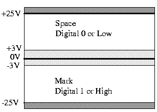
The receiving side recognizes a Space (digital 0 or Low) as any voltage between +3 and +25V and a Mark (digital 1 or High) as any voltage between -3 and -25V. The standard allows for a voltage loss through the cable and noise immunity by reducing the receive requirements to +/-3 Volts!
|
Pin
|
Name
|
Description
|
EIA Circuit
|
|
1
|
GND
|
Chassis ground
|
AA
|
|
2
|
TXD
|
Transmit Data (TXD)
|
BA
|
|
3
|
RXD
|
Receive Data (RXD)
|
BB
|
|
4
|
RTS
|
Ready to Send
|
CA
|
|
5
|
CTS
|
Clear to Send
|
CB
|
|
6
|
DSR
|
Data Set Ready (DCE Ready)
|
CC
|
|
7
|
SGND
|
Signal ground
|
AB
|
|
8
|
DCD
|
Carrier Detect (CD or RLSD)
(RLSD - Received Line Signal Detector)
|
CF
|
|
9
|
n/u
|
|
|
|
10
|
n/u
|
|
|
|
11
|
n/u
|
|
|
|
12
|
DCD2
|
Secondary Carrier Detect (SRLSD)
|
SCF
|
|
13
|
CTS2
|
Secondary Clear to Send
|
SCB
|
|
14
|
TXD2
|
Secondary Transmit Data
|
SBA
|
|
15
|
TxSigC
|
Transmitter Signal Element Timing - DCE
|
DB
|
|
16
|
RXD2
|
Secondary Receive Data
|
SBB
|
|
17
|
RxSig
|
Receive Signal Element Timing - DCE
|
DD
|
|
18
|
LL
|
Local Loopback
|
|
|
19
|
RTS2
|
Secondary Ready to Send
|
SCA
|
|
20
|
DTR
|
Data Terminal Ready (DTE Ready)
|
CD
|
|
21
|
SQ/RL
|
Signal Quality/Remote Loopback
|
CG
|
|
22
|
RI
|
Ring Indicator
|
CE
|
|
23
|
DSRS
|
Data Signal Rate Selector
|
CH/CI
|
|
24
|
TxSigT
|
Transmitter Signal Element Timing - DTE
|
DA
|
|
25
|
TM
|
Test Mode
|
|
The signals in Bold/Italic are required for a basic asynchronous modem connection.
|